Introduction
The purpose of this blog is to design an own filter with a specific cutoff frequency by choosing one of the filter types among Butterworth, Bessel, Cheby1, and Cheby2, Elliptical filter, and its order with ideal OPAMP. Also, the implementation of the filter is given by Direct Form 1(DF1), DF2, Parallel, and other implementations. The filter characteristics are roughly divided into the Butterworth, Bessel, Cheby1, and Cheby2, Elliptical filter, and each filter has some unique characteristics.
- Butterworth – The Butterworth filter has no ripple in both the passband and stopband and the frequency response is as flat as possible in the passband. (Maximally flat magnitude filter)
- Bessel – The filter has amplitude characteristics similar to Butterworth characteristics but is approximated to optimize to obtain better transient response characteristics in the passband. Therefore, the amount of overshoot is small, and the rise speed is the fastest as compared with the filter having the other characteristics of the same order.
- Cheby1 (Chebyshev) – The Cheby1 filter is a low pass filter with equiripple in the passband. A steep cutoff characteristic can be obtained by allowing ripples.
- Cheby2 (Inverse Chebyshev) – The Cheby1 filter is a low pass filter with equiripple in the passband. A steep cutoff characteristic can be obtained by allowing ripples.
- Elliptical – The Cheby1 filter and the Cheby2 filter have a steeper cutoff characteristic than the Butterworth filter by providing equiripples in either the passband or the stopband. On the other hand, the elliptical filter is created based on obtaining steeper cutoff characteristics by generating equiripples in both the passband and stopband.
Implementation of Python
Out of these 5 filter types, I chose 7th order Butterworth low pass filter targeting 10kHz cutoff frequency for this project because the Butterworth filter is easier to implement with no ripples in both the passband and the stopband. The 7th order Butterworth low pass filter has seven filter coefficients in the denominator and a filter coefficient in the numerator. Then, the Python code below can generate these coefficients and its Bode Plot from the obtained transfer function.
|
1 2 3 4 5 6 7 8 9 10 11 12 13 14 15 16 17 18 19 20 21 22 23 24 25 26 27 28 29 30 31 32 33 34 35 |
from scipy import signal import matplotlib.pyplot as plt import numpy as np f1 = 24 f2 = 10000 order = 7 w1 = 2*np.pi*f1 w2 = 2*np.pi*f2 B, A = signal.iirfilter(order, w2, btype='low', analog=True, ftype='butter', output='ba') w, h = signal.freqs(B,A) # w: Angunlar frequency, h: Frequency response # Plot the magnitude fig, ax1 = plt.subplots() mag = 20 * np.log10(abs(h)) ax1.plot(w/2/np.pi, mag, color='red', linewidth=2) ax1.set_title('Butterworth low pass filter frequency response', fontsize=20) ax1.set_xlabel('Frequency [Hz]', fontsize=20) ax1.set_ylabel('Amplitude [dB]', fontsize=20) ax1.axvline(f2, color='blue', linewidth=2) # cutoff frequency #Plot the phase ax2 = ax1.twinx() # A twin axes sharing the x axis rad = np.unwrap(np.angle(h)) degree = np.rad2deg(rad) ax2.plot(w/2/np.pi, degree, color='green', linewidth=2) ax2.set_ylabel('Phase [rad]', fontsize=20) plt.xscale('log') plt.margins(0, 0.01) plt.grid(which='both', axis='both') plt.show() print "a=", A print "b=", B |
|
1 2 3 4 5 |
a= [1.00000000e+00+0.00000000e+00j 2.82363785e+05-4.18544220e-11j 3.98646534e+10-1.40255514e-05j 3.61949759e+15-1.76250277e+00j 2.27419741e+20-1.66111973e+05j 9.88843579e+24-6.95808205e+09j 2.76508404e+29-2.86905405e+14j 3.86597533e+33-4.29209483e+18j] b= [3.86597533e+33+0.j] |
When executing the Python code, the ideal Bode Plot will be observed like the image below. As you can see, this simulation of 7th order Butterworth low pass filter in Python has 10kHz cutoff frequency, and the attenuation slope is -140dB/dec.

Implementation using a Behavioral Voltage Source
The following transfer function is generated from the filter coefficients obtained by executing Python.

Then, open the LTSpice and the Bode plot of the 7th order Butterworth low pass filter can be simulated by using an ideal behavioral voltage source based on the coefficients from the transfer function obtained in Python.
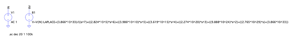
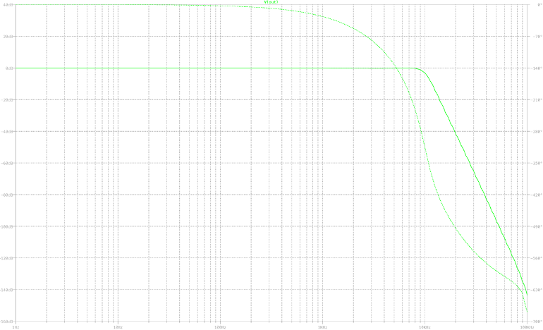
When starting to simulate the ideal behavioral voltage source using Laplace Transform function in LTSpice, the Bode plot below was observed.

Implementation using a Direct Form 2
Next, I choose the direct form 2 implementation for the 7th order Butterworth low pass filter out of these implementations. In order to design the 7th order Butterworth lowpass filter by using DF2, there are some resistors that should be determined by each coefficient in the transfer function and the resistance of Rf determined by own. This table represents all values you need for the circuit by DF2.
| Stage | Coefficients | Stage Gain | Gain provided by Summer | Rf (Ω) | Ra (N) | Gain + side Summer |
|---|---|---|---|---|---|---|
| 1 | 2.824E+05 | 6.283E+04 | 4.494 | 1.0E+05 | 2.225E+04 | 30.1826 |
| 2 | 3.986E+10 | 6.283E+04 | 10.0976 | 1.0E+05 | 9.903E+03 | Gain - side Summer |
| 3 | 3.619E+10 | 6.283E+04 | 14.591 | 1.0E+05 | 6.854E+03 | 29.1825 |
| 4 | 2.274E+20 | 6.283E+04 | 14.591 | 1.0E+05 | 6.854E+03 | Gain Difference |
| 5 | 9.888E+24 | 6.283E+04 | 10.0976 | 1.0E+05 | 9.903E+03 | 1.0001 |
| 6 | 2.765E+29 | 6.283E+04 | 4.4939 | 1.0E+05 | 2.2252E+03 | R dummy |
| 7 | 3.866E+33 | 6.283E+04 | 1 | 1.0E+05 | 1.000E+03 | 9.9990E+04 |
Also, this is the signal flow graph for the direct form 2 realization of the 7th order Butterworth low pass filter.

Based on the values determined and the realization, the circuit of the 7th order Butterworth low pass filter by DF2 can be finally designed like this!

When observing the voltage output in LTSpice, the Bode plot below was simulated. The magnitude of the 7th order Butterworth low pass filter is pretty close to the magnitude generated by Python implementation and by the ideal behavioral voltage source.
Conclusion
The cutoff frequency and phase change of the 7th order Butterworth low pass filter using ideal OPAMPs generated by Python and by the simulation in LTSpice was matched at 10kHz and -630°. In addition, the attenuation slope was -140dB/dec. It would be more fun if I have simulated my own filter with different orders and different methods of implementation on LTSpice by comparing the ideal Bode plot simulated by Python. See you for the next project!