Objective
The objective of this post is to understand how to model a 2-bit comparator and a 4-bit comparator in Verilog. Firstly, a 2-bit comparator is implemented based on the logic expressions from the truth table of each output. Next, likewise, it generates a 4-bit comparator by instantiating two models of the 2-bit comparators and some extra logic gates. Also, the actual results of each output corresponding to the inputs will be observed on the Nexys board based on the own testbench file.
Environment, Tool, and Board
- Ubuntu 16.04
- Vivado 2018.3
- Nexys A7 100T (Family: Artix-7, Package: csg324, Speed: -1L)
- Part: xc7a100ticsg324-1L)
A 2-bit comparator
The truth table of a 2-bit comparator can be represented by the table shown below. Each input (a1, a0, b1, b0) can contain 1 bit of data, and each data will be going into the comparator to compare the size of the data. In the table, the output G stands for “Greater” which means a1a0>b1b0. Likewise, the output E stands for “Equal” which means a1a0=b1b0, and the output L stands for “Lower” which means a1a0<b1b0.
| a1 | a0 | b1 | b0 | G | E | L |
|---|---|---|---|---|---|---|
| 0 | 0 | 0 | 0 | 0 | 1 | 0 |
| 0 | 0 | 0 | 1 | 0 | 0 | 1 |
| 0 | 0 | 1 | 0 | 0 | 0 | 1 |
| 0 | 0 | 1 | 1 | 0 | 0 | 1 |
| 0 | 1 | 0 | 0 | 1 | 0 | 0 |
| 0 | 1 | 0 | 1 | 0 | 1 | 0 |
| 0 | 1 | 1 | 0 | 0 | 0 | 1 |
| 0 | 1 | 1 | 1 | 0 | 0 | 1 |
| 1 | 0 | 0 | 0 | 1 | 0 | 0 |
| 1 | 0 | 0 | 1 | 1 | 0 | 0 |
| 1 | 0 | 1 | 0 | 0 | 1 | 0 |
| 1 | 0 | 1 | 1 | 0 | 0 | 1 |
| 1 | 1 | 0 | 0 | 1 | 0 | 0 |
| 1 | 1 | 0 | 1 | 1 | 0 | 0 |
| 1 | 1 | 1 | 0 | 1 | 0 | 0 |
| 1 | 1 | 1 | 1 | 0 | 1 | 0 |
It is possible to extract the logic expressions of each output from the table. However, in order to minimize the use of gates, the Karnaugh map (K-map) can be useful.
Logic Expression for output G
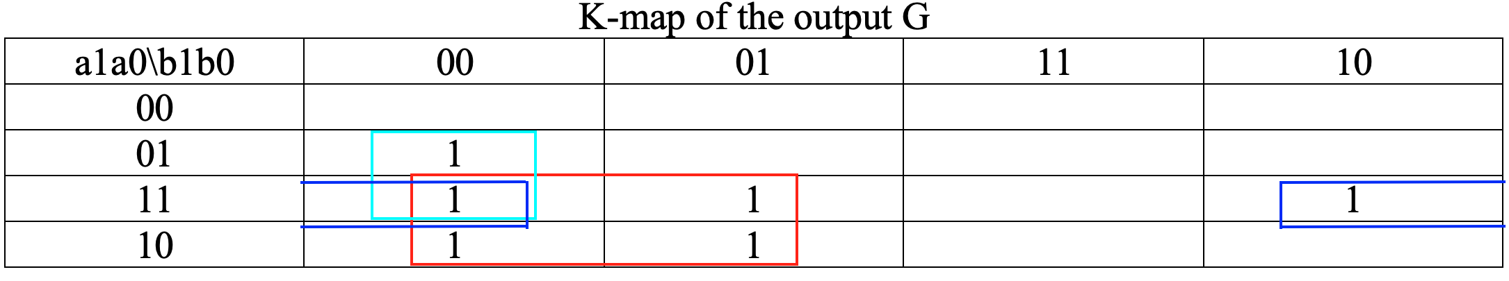
G (a1a0>b1b0) = a1b1′ + a0b1′ b0′ + a1a0b0′
Simplifying to reduce the number of the gates by using XNOR gate,
G = a1b1′ + (a1⨀b1)a0b0′
Logic Expression for output E
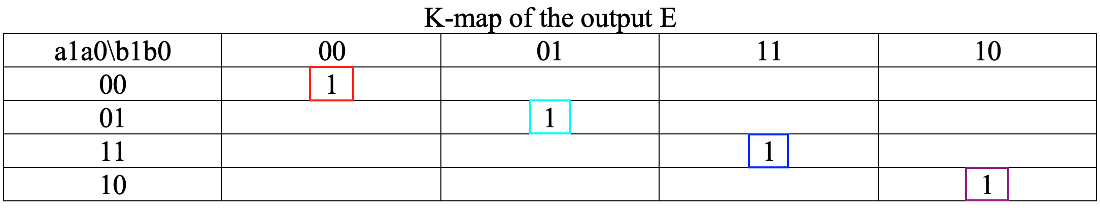
E (a1a0=b1b0) = a1’a0’b1’b0′ + a1’a0b1’b0 + a1a0b1b0 + a1a0′ b1b0′
Simplifying to reduce the number of the gates by using XNOR gate,
E = (a1⨀b1)(a0⨀b0)
Logic Expression for output L
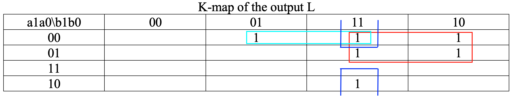
L (a1a0<b1b0) = a1’b1 + a1’a0’b0 + a0’b1b0
Simplifying to reduce the number of the gates by using XNOR gate,
L = a1’b1 + (a1⨀b1)a0’b0
A 4-bit comparator in Verilog
Comparing to the truth table of a 2-bit comparator, a 4-bit comparator will be used 4-bit in input A and 4-bit in input B. Therefore, the truth table of the 4-bit comparator is the following table below.
| a3b3 | a2b2 | a1b1 | a0b0 | G | E | L |
|---|---|---|---|---|---|---|
| a3 > b3 | x | x | x | 1 | 0 | 0 |
| a3 < b3 | x | x | x | 0 | 0 | 1 |
| a3 = b3 | a2 > b2 | x | x | 1 | 0 | 0 |
| a3 = b3 | a2 < b2 | x | x | 0 | 0 | 1 |
| a3 = b3 | a2 = b2 | a1 > b1 | x | 1 | 0 | 0 |
| a3 = b3 | a2 = b2 | a1 < b1 | x | 0 | 0 | 1 |
| a3 = b3 | a2 = b2 | a1 = b1 | a0 > b0 | 1 | 0 | 0 |
| a3 = b3 | a2 = b2 | a1 = b1 | a0 < b0 | 0 | 0 | 1 |
| a3 = b3 | a2 = b2 | a1 = b1 | a0 = b0 | 0 | 1 | 0 |
From the table above, the logic expressions of each output are:
G = a3b3′ + (a3⨀b3)a2b2′ + (a3⨀b3)(a2⨀b2)a1b1′ + (a3⨀b3)(a2⨀a2)(a1⨀b1)a0b0′
E=(a3⨀b3)(a2⨀a2)(a1⨀b1)(a0⨀b0)
L = a3’b3 + (a3⨀b3)a2’b2 + (a3⨀b3)(a2⨀b2)a1’b1 + (a3⨀b3)(a2⨀a2)(a1⨀b1)a0’b0
By combining all knowledge learned so far, the source code of the 4-bit comparator in Verilog is:
|
1 2 3 4 5 6 7 8 9 10 11 12 13 14 15 16 17 18 19 20 21 22 23 24 |
`timescale 1ns / 1ps module four_bit_comp(G, L, E, a0, a1, a2, a3, b0, b1, b2, b3); input a0, a1, a2, a3, b0, b1, b2, b3; output G, L, E; wire g1, g2, l1, l2, e1, e2; two_bit_comp comp1(g2, l2, e2, a3, a2, b3, b2); two_bit_comp comp2(g1, l1, e1, a1, a0, b1, b0); assign G = (g2)|(e2&g1); assign L = (l2)|(e2&l1); assign E = e1&e2; endmodule module two_bit_comp(G, L, E, a1, a0, b1, b0); input a1, a0, b1, b0; output G, L, E; assign G = ((a1)&(~b1))|(((a1)~^(b1))&((a0)&(~b0))); assign L = ((~a1)&(b1))|(((a1)~^(b1))&((~a0)&(b0))); assign E = (a1~^b1)&(a0~^b0); endmodule |
Then, it can generate a schematic of the 4-bit comparator when clicking “Open Elaborated Design” in Flow Navigator on the left side.
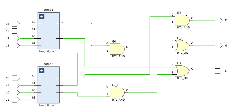
As observed from the schematic, there are two 2-bit comparators and few gates to implement the 4-bit comparator in Verilog. In addition, the constraint file for the 4-bit comparator can be found on Github designed by Digilent.
|
1 2 3 4 5 6 7 8 9 10 11 12 13 14 15 16 17 18 |
# NEXYX A7 Pin Assignments ############################### ## On-board Slide Switches ## ############################### set_property -dict { PACKAGE_PIN J15 IOSTANDARD LVCMOS33 } [get_ports { b0 }]; # swt[0] set_property -dict { PACKAGE_PIN L16 IOSTANDARD LVCMOS33 } [get_ports { b1 }]; # swt[1] set_property -dict { PACKAGE_PIN M13 IOSTANDARD LVCMOS33 } [get_ports { b2 }]; # swt[2] set_property -dict { PACKAGE_PIN R15 IOSTANDARD LVCMOS33 } [get_ports { b3 }]; # swt[3] set_property -dict { PACKAGE_PIN R17 IOSTANDARD LVCMOS33 } [get_ports { a0 }]; # swt[4] set_property -dict { PACKAGE_PIN T18 IOSTANDARD LVCMOS33 } [get_ports { a1 }]; # swt[5] set_property -dict { PACKAGE_PIN U18 IOSTANDARD LVCMOS33 } [get_ports { a2 }]; # swt[6] set_property -dict { PACKAGE_PIN R13 IOSTANDARD LVCMOS33 } [get_ports { a3 }]; # swt[7] ############################ ## On-board LEDs ## ############################ set_property -dict { PACKAGE_PIN V17 IOSTANDARD LVCMOS33 } [get_ports { L }]; # led[5] set_property -dict { PACKAGE_PIN U17 IOSTANDARD LVCMOS33 } [get_ports { E }]; # led[6] set_property -dict { PACKAGE_PIN U16 IOSTANDARD LVCMOS33 } [get_ports { G }]; # led[7] |
Simulation
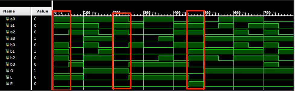
The objective of the post is to compare the simulated waveform and actual observation on the Nexys board, so the waveforms can be randomly generated by using the random function in the testbench.
|
1 2 3 4 5 6 7 8 9 10 11 12 13 14 15 16 17 18 19 20 21 22 23 |
`timescale 1ns / 1ps module four_bit_tb(); reg a0, a1, a2, a3; reg b0, b1, b2, b3; wire G, L, E; four_bit_comp dut(G, L, E, a0, a1, a2, a3, b0, b1, b2, b3); initial begin repeat(16) begin a0 = $urandom_range(0, 15); a1 = $urandom_range(0, 15); a2 = $urandom_range(0, 15); a3 = $urandom_range(0, 15); b0 = $urandom_range(0, 15); b1 = $urandom_range(0, 15); b2 = $urandom_range(0, 15); b3 = $urandom_range(0, 15); #50; end end endmodule |
Final Result on Nexys Board
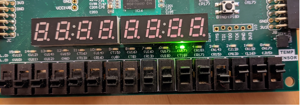
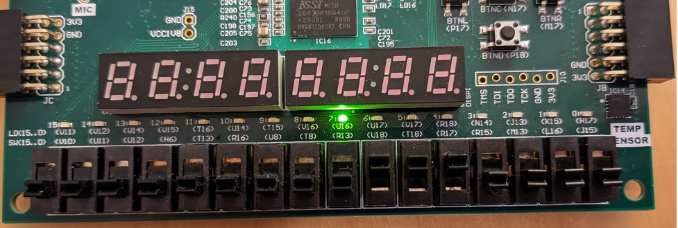
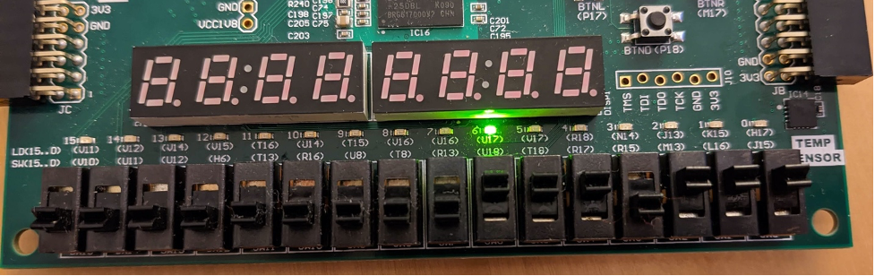
This time, I tested the part surrounded by red with Nexus board. Comparing the behavioral simulation with the actual results observed as LED output, it can be seen that it is working properly.
DONE! Please leave a comment if you have any questions.